For the insulation systems used in transformers, motors, etc., the EIS test procedures are found in:
UL STANDARD 1446 Test Procedures for Electrical Insulation Systems
- UL or a UL-approved test lab constructs the
candidate and control test rigs. Ten rigs are constructed for each test temperature, for
both the control and candidate systems. After the test rigs are constructed, a UL
engineer approves the contruction and records the ingredients; this engineer will
typically oberve the start-up of the first cycle. Test cycles then proceed as follows:
- Highest temperature: 3-day cycle
Next lower temperature: 7-day cycle
Next lower temperature: 14-day cycle
Lowest temperature: 28-day cycle
Test at end of each cycle
- Hold until stabilized at -20°C (-4°F)
- Vibration at 60 Hz
1 hr for motorettes
3 min for transformerettes
- Hold for 48 hr at 92 to 100% relative humidity at room temperature.
- Test rigs are dielectric stressed by 600 V applied phase-to-phase and
phase-to-ground and 120 V turn-to-turn, each 10 min. (It is required
that the lowest test temperature shall result in a geometric mean
time to end-of-life of at leat (5000 hrs.)
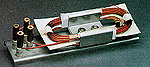 Manufacturers can test their actual equipment or they can substitute a "motorette" or
"transformerette" that represents their system.
Manufacturers can test their actual equipment or they can substitute a "motorette" or
"transformerette" that represents their system. The motorette pictured can be used to simulate the actual component.
This test procedure qualifies the major components of the insulation sytsem. Major components include ground insulation, magnet wire, interwinding insulation, and varnishes. However, the dip varnish can also be considered a minor component if the motorette or transformette did not use a varnish. The varnish, like other minor components, can be added to insulation systems by sealed-tube testing.
SEALED TUBE TESTING
Sealed tube testing was devised so that additional materials could be added to the original EIS without going through the full, very laborious motorette or transformerette testing discussed above. Tapes, lead wires, sleeving materials, and dip varnishes can be added to various insulation systems using the sealed tube procedure described below.
UL Standard 1446 Sealed Tube Procedure
- Reference Tube. This tube contains only materials employed in the original
insulation system.
- Minor Component Tube. This tube contains all new or substitute materials plus
all materials and alternates currently used in the approved insulation system.
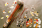
- Cleaning. Tubes are first cleaned and dried as needed.
- Loading. Twisted wire pairs are inserted in tubes, followed by the component
materials, avoiding contact with the magnet wire if possible.
- Sealing. Filled glass tubes and the sealing materials are dried 1 hr at 105°C.(221°F)
Tubes are then sealed immediately and cooled to room temperature.
- Sealed tubes are conditioned 336 hr at a temperature equal to the class rating of the
system plus 25°C (45 °F); for example, the temperature for Class 155 (F) would be
180°C. (356°F)
- Tubes are cooled to room temperature and then opened just prior to evaluation. Twisted
pairs are stressed until breakdown by increasing the test voltage at a maximum rate
of 500 V per second. (Results for the original system components and the new
components are compared. The dielectric strength of the new samples cannot be less
than 50% of the original.)
 These materials are then dried at 105°C (221°F), for one hour and loaded into a tube. This tube is then sealed (hence the name sealed tube) and cooled to room temperature and placed into an oven at 25° C above the system rating (for example, 155 ° C for a Class 130 (B) system ) for two weeks (336 hours).
The results of these tests are "recognized" EIS, which are listed in the UL "Yellow Cards" in two places: as UL 1446-recognized EIS and again as IEC 850-recognized EIS. For UL 1446 systems, the listing at UL is under "Plastic Materials and Electrical Insulation Systems (OBJS2). " The EIS listed under IEC 85 are found in the UL "Yellow Cards" under "Insulation System Components, Electrical, Evaluated in Accordance with IEC Publications (OCTU2)."


 at sales@pleo.com
 ® Registered trademark of Underwriters Laboratories, Inc.
 ® is P. Leo & Co., Ltd. trade mark.